Tuesday 31 May 2016

ORIGINAL TUTORIALS AND REFLECTION FINAL SUBMISSION

1) Link to Blog

2) Link to First Tutorial


4) Link to Reflection


REFLECTION

This BEIL course provides an excellent opportunity for students to undertake in a task which they likely may not partake in often. The process of metal shaping (through the use hand tools and manual labour work) is something relatively new to most students. This course provides a new perspective and experience in designing; a concept embedded within all students of Built Environment faculty. By partaking in this BEIL course, students of a wide variety of disciplines and fields are gifted with the opportunity to collaborate and learn from each other.

Numerous processes of 'fabrication' were explored within this subject, ranging from 3D modelling, laser cutting and metal shaping, all of which are individual processes yet can be combined to create an object. This course has been successful in encouraging students think before design and to work backwards, whereby a desired effect is chosen and then a method is made. However, the beauty of the metal shaping exercises are that there is large room for trial and error, where the malleability of metal sheeting does not act as a limitation but provides areas for change and lessons to be learnt.

As an architecture student, this BEIL course has also gifted some new and interesting insights into the fabrication of building materials and concept of design. Quite similar to the design of a building or structure, a 'shape' is designed and thought is placed into how it will be constructed. The metal shaping exercises have provided the experience of thinking backwards where a look determines the method. Conversely, architecture and construction follows the opposite process. The tasks of metal shaping have also exhibit the importance of finer details and achievement of these details, a feature architects often overlook due to the working scales. Architects are constantly challenging the idea of buildability, feasibility and possibility, with their designs and ideas. Using the ideas, concepts and processes learnt from this subject, they can also be reiterated into architectural coursework in design studios and model making, allowing more complex customised shapes to be hand made where previously would be considered impossible.

With the skills and knowledge gained in the BEIL course, students of all disciplines within the Built Environment faculty can learn many beneficial skills, but more importantly thought processes and concepts which can highly improve their way of thinking. This course encourages students to develop their creativity in design, sense of problem solving but most importantly to get out there and have fun.


Curved metal architecture (Source: Frank Gehry's Guggenheim Museum Bilbao)


INTERDISCIPLINARY TUTORIAL

By outlining a series of tips and guidelines for the interdisciplinary metal shaping exercise, these should provide the average layman with the necessary knowledge and support to be successful in metal shaping.


  • The choice of the interdisciplinary object was mixed in its difficulty. As it was a much more generic and simple shape it was quite easy to fabricate, however as it is traditionally an object produced using factory machinery it is quite difficult to duplicate.
  • A chosen shape for metal shaping should ideally be a more curvilinear and organic object, due to the nature of the tools available for metal shaping. Factory / machine made objects are much more difficult to replicate using human hands and tools, whereas a shape more commonly hand-made is easier to reproduce.

  • The procedure of metal shaping requires thought and decision of where to begin, whereby completing a task which does not obstruct or restrict a task which is required later on. This was exhibited where bending was first applied to the shape in order to create a shovel tray; a task which needed to be complete first as following the shaping of the central curve it would be impossible to fit the skin within the bending brake.
  • Caution must be utilised in using the bending brake, in order not to over-compensate / over-bend more than required. Although reversible, this creates slight stretching and scratching of the sheet.


Overbending created by bending brake

  • Additionally, it is also optimal to use the correct amount and size of plates, as it is more functional and effective to create a single bend as opposed to multiple consecutive bends. This also reduces the creation of cracks and scratches.


Using a single bending plate can cause buckling and unwanted movements within sheet


Overuse of bending brake can create unwanted scratches and tears

  • In order to fabricate a smooth and accurate curve, a variety of anvils (of which are available in the Squarehouse workshop) can be applied to use. However, these should be used sparingly and with caution as the incorrect size of the anvil may result in over-stretching (requiring re-shrinking) or possibly irreversible changes.


Oval steel dolly anvil


Tapered Steel T-Dolly anvil; although a curve can be achieved with both, correct selection of anvil will allow for more efficient less time-consuming work

  • The process of cutting and trimming should be a task that is completed at the beginning of the metal shaping process. This allows for cleaner and more accurate cuts to be made, as there are no indentations or contours within the metal sheet. Where possible the guillotine should be used, due to its ability to create a long, quick cut, with the least chance of an off-cut or inaccuracy.


Manual Treadle Guillotine

  • In order to create a curved or angled cut, the hand lever shear should be chosen over the tin-snips due to its stronger and more accurate cut. The improved accuracy and strength is reflected in its ability to reduce miscuts and burred edges.


Hand lever shear


Burred edges and miscuts from bad cutting


Bent, protruding miscut

  • Through the use of different hammers and tools, different types of indentations and changes can be implemented into the metal sheet. The different radius ends of the nyoln bossing mallet can create different indents into the sheet metal, with a choice to be made of which is more suitable and necessary (with the least chance of creating an unwanted or reversible effect). The cross chisel steel hammer can produce a indent that is much more sharp and pointed, and due to its strength of material is can create a bolder more visible indentation.


Flat end mallet


Small end of bossing mallet


Large end of bossing mallet


Steel cross chisel hammer

  • A major lesson learnt during metal fabrication was to use other materials to create your own 'anvils' or metal shaping tools. Through the simple use of space timber pieces or cutting suitable pieces, it is quite easy to produce an 'anvil' to allow for implementation of a desired shape or effect on the sheet metal.


Timber pieces can be used to 'mould' metal sheet


FIRST TUTORIAL

In order to be successful in fabrication of the original chosen shape, I have provided guidelines, tips and ideas during each process, which hopefully will enable an average layman with little knowledge of metal shaping to understand the concepts involved.


  • In regards to choosing an object for fabrication, it is most favourable to select an item which is not too complicated, and does not have a multitude of curves.
  • Unfortunately my object, the human hand, was an object that is quite hard to replicate due to the numerous crevasses, movements and directions which the 'shape' has.

  • During the photogrammetry phase using AutoDesk's 123D Catch, it is highly beneficial to be thorough and attentive in scanning and modelling of the chosen shape; reducing the possibility of mistakes and need to re-scan later on.
  • The object should be scanned in an environment with generous amounts of sunlight, allowing the photos taken using the app to be clear and unobstructed.
  • Additionally, a large range of photographs upon the object's X, Y and Z axis should be taken, providing a 360 degree view around the shape but also in its height and verticality. There should not be a limited placed on the required number of photographs, as the more taken the more detail can be implemented into the modelling of the object.
  • If there is a need to remodel or repair the scanned object, AutoDesk's Meshmixer should be used to smooth out any inconsistencies and patch up any 'holes' picked up during the scan. In particular the 'Flatten' and 'ShrinkSmooth' functions are the most useful to create a neat and even shape.

  • During the construction phase of the template, thought should be placed into the material in which the template is to be made.
  • The method of construction method should be firstly trialed in AutoDesk's 123D Make, as it will provide an estimation to the structural possibility of each shape using different methods. This also displays an estimation to the amount of materials necessary, and this is a useful feature as it can eliminate wastage and ultimately provide the most (cost and time) efficient method. 
  • An object that is modeled using the 'interlocking' or 'radial' method should avoid softer materials such as Boxboard, White Card or Balsa wood, due to its softer density.
  • Materials such as plywood or acrylic as they would be recommended, as they are highly sturdy and provide a degree of structure to the shape.
  • Furthermore, the construction method of the shape should reflect the shape of the template, whereby an object which is directed horizontally would utilise the 'vertical stacking' method.

  • The process of shaping such a delicate and complex object was quite difficult, due to the multiplex of contours and movements.
  • It is essential to use a type of aluminum metal sheet that is the correct thickness, which would allow for easier malleability and movability. As learnt from my own experience of metal shaping with both thin and thick aluminum, the thicker sheet (although is more susceptible to harder hitting) is much more difficult to shape.
  • The necessity to properly mark out the areas which need to be 'shaped' should not be ignored, because during the metal shaping process, the movement of the metal can result in confusion and 'loss of bearings' within the sheet.
  • During any process of shaping the metal, whether it is shrinking, stretching or bending, it is highly recommended to stop approximately 5 - 10 millimetres before the line in order to account for movements when proceeded to the next task.
  • A general rule of thumb during this process was to avoid 'stretching' the metal sheet more than is necessary, as it is almost impossible to shrink an overstretched area.
  • A great degree of care should be used when using the 'shrinker stretcher', where due to its many 'teeth' it can easily imprint 'teeth marks', scratches and even tears in the skin of the metal sheet.

Shrinker Stretcher


Shrinker stretcher must be used in moderation


Overuse can create bends


Tears from overuse

  • Although polishing can be used during finalisation of the shape, it is not entirely sucessful in removing scartches and stretch marks produced by the shinker stretcher. As a result, it may be considered to avoid this machine completely and use the more traditional method tree stump stretching.


Partially polished shape, with highly visible stretch marks

  • Consideration should be placed upon choice of tools, as each tool although can provide similar effects is also different in its strength and hardness. Nylon mallets are able to produce a strong and defined 'indent' into the metal sheet (at times leaving marks when used against an anvil or sandbag), whereas wood mallets provide a more gentle and less intrusive method of metal shaping when used with anvils and timber blocks.


Nylon Mallet


Wooden Mallet

  • Finally, there are a wide variety of anvils and tools available within the Squarehouse workshop, and these can be used to achieve a multitude of curves, contours and shapes. Although these may appear similar, it is important to select the correct anvil (in terms of size), as it will determine the degree of stretch in which is imparted into the shape. Once a stretch has been created on a metal sheet, it is much more difficult (and should be avoided when possible) to shrink.


Different sized mushroom steel dome dollies


Tuesday 17 May 2016

INTERDISCIPLINARY OBJECT AND SKIN - FINAL SUBMISSION

1) Link to Blog

2) Link to Interdisciplinary Object

3) Link to Draft Interdisciplinary Skin

4) Link to Metal Shaping of Interdisciplinary Object

5) Link to Interdisciplinary Object and Skin

INTERDISCIPLINARY OBJECT AND SKIN

The interdisciplinary shape of the shovel was relatively easy to mimic, due to its simplistic form. As a profile with only three upwards bends, two side bends and a central curved shaft, it was not a difficult shape to fabricate. Although the fit of the skin with the contours of the interdisciplinary object is not entirely perfect, the overall profile of the skin matches quite well with the shape in which it was modeled after. The most difficult region of the skin to shape was the central curve of the object, due to it high degree of curvature given the small scale of the object. This process emphasised how precise yet rigid manufactured objects can be, due to the nature in which shovels are produced. Machinery and equipment which is used to produce these tools are highly accurate and it is difficult and somewhat impossible for it to replicated using hand tools and more traditional methods of metal shaping.


Interdisciplinary object - Shovel


Side view of shovel template


Metal skin of object


Side view of skin showing upward bends


Front view of skin showing upward bending shovel tray


Skin showing curve of shovel shaft


Skin on object showing wrapping of curvature


Side view of skin placed on object


Front view of skin placed on object


Metal skin pulled back to show curvature fit


Final interdisciplinary object and skin


METAL SHAPING OF INTERDISCIPLINARY OBJECT

Moving forward from the lessons learnt during the draft of the interdisciplinary object, the process of creating a final skin for the object required rearranging of steps and tweaks to the chosen methods of metal shaping. In order to be more precise in metal shaping, lines were again marked out onto the aluminium metal sheet to mark where the shape bends, creases and curves. However this time, the exact movements of the central curve were also measured and marked out. It was found that the central shaft of the shovel object straightens for 10cm before angling inwards as it reaches the second bend line of the shovel tray. This therefore created a shape which had a difference in width of the central shaft to be 0.5cm's on each side and would begin to merge inwards. In addition, it was also found that the height of the central curved shaft also reduces and flattens as it approaches the second bend of the shovel tray.


Template was placed over sheet to mark movement points


Line markings to dictate movement of central curve


The first step in shaping of the metal sheet was to implement the three bends in the profile of the sheet, creating the 'dip' of the shovel tray. This was achieved by placing the metal sheet into the metal bending brake and bending it slightly upwards along the marked crease lines.


Metal sheet in metal bending brake

By creating bends to the metal sheet before creating any other changes to the structure or shape of the aluminium, the would be no need to create bends later on during the process. It would also be easier to create the final shape of the skin, as it was impossible to create the bends after previously creating the central curve (as learnt during the draft experimentation). Additionally, by creating bends to the shape of the metal, it would retain its shape and provide a visual indication (as opposed to merely marked guide lines) of the areas of the metal that would be required to 'move'.

The next required step was to create the central curve of the shape. Similar to the process undertaken during the draft shape, this was achieved by using the small end of a bossing mallet to hit the metal into a sandbag, creating a line of 'dents' along the marked area of the sheet. In order to further the depth and shape of the curve the metal sheet was hit into two pieces of timber held in place using G clamps, accentuating the depth of the curve.


Timber squares G Clamped down spaced in accordance to curve width


The timber squares were angled inwards, mimicking the shape of the shovel shaft


In order to prevent the metal from stretching / moving in the wrong direction, a solid definition along the edges of the central curve would needed to be made. This was achieved by placing a tall piece of timber inside a vice, allowing the metal sheet to be hung off the edge and hit using a rubber mallet with a pointed edge.


Timber piece in vice and pointed edge rubber mallet


Metal sheet hit against edge of timber piece to define junction


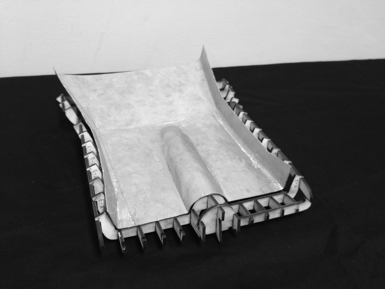
Once the edge and rough shape of the shovel shaft was established, the depth of the dip needed to match that of the shape, in order to achieve a fit with the skin. By taking the metal sheet back to the two timber G clamp pieces, the aluminium sheet was hit constantly against it creating further depth to the curve. Simultaneously, this was measured up against a slice of the laser cut template in order to achieve the correct depth, radius and curvature of the central curve.


By matching up the template and shape the side gaps were reduced


Depth of curve was increased and sides were 'pushed' inwards to meet shape


Once the skin of the central curve was almost to completion, edges the metal sheet had to be bent inwards in order to create the side 'flaps' / 'wings'. Similar to how an actual shovel is manufactured; using machinery to press steel, this same concept was incorporated to the bending of the metal skin. In order to determine the edges and lines along which the metal sheet would be bend, the laser cut object was placed on top of the metal skin and the points at which the sheet moves / bends were dotted. By joining of the dots at which there is movement, guide lines were marked out.


Bend lines were marked out


Returning to the metal bending brake, the previously marked lines were bent upwards, reflecting the shape of the laser cut template.


Metal bending brake to create an upwards flap / wing to the metal skin


A difficultly experienced whilst bending the shape rose as the bend lines were not parallel with each other. As a result a bend in one line created an inverse bend in another, and an additional bend would at times negate and create buckling of a previous bend. However, it was found that the best and most effective option was to bend along the lines regardless and to use metal shaping techniques to smooth out unwanted bend lines and creases. By using a flat rubber mallet, unwanted bends and buckling was able to be plateaued. This was achieved by again placing the metal sheet upon two pieces of timber and hitting the metal to flatten any movements.


Hitting against timber pieces allowed flattening of sheet metal


Moreover, an unwanted effect of using the metal bending brake also created a slight movement to the profile of the central curve, with slight bucking and mashing of curvature. In order to reverse this, the metal sheet was hit against the edge of the timber pieces to redefine the edges of the curve, locking any movement of the shape. Furthermore, the metal sheet was hit over the end of the timber square in order to create a higher degree of bend to the side 'flaps', in order to match that of the laser cut template.


Edges were hit over edge of timber to bend inwards, matching object


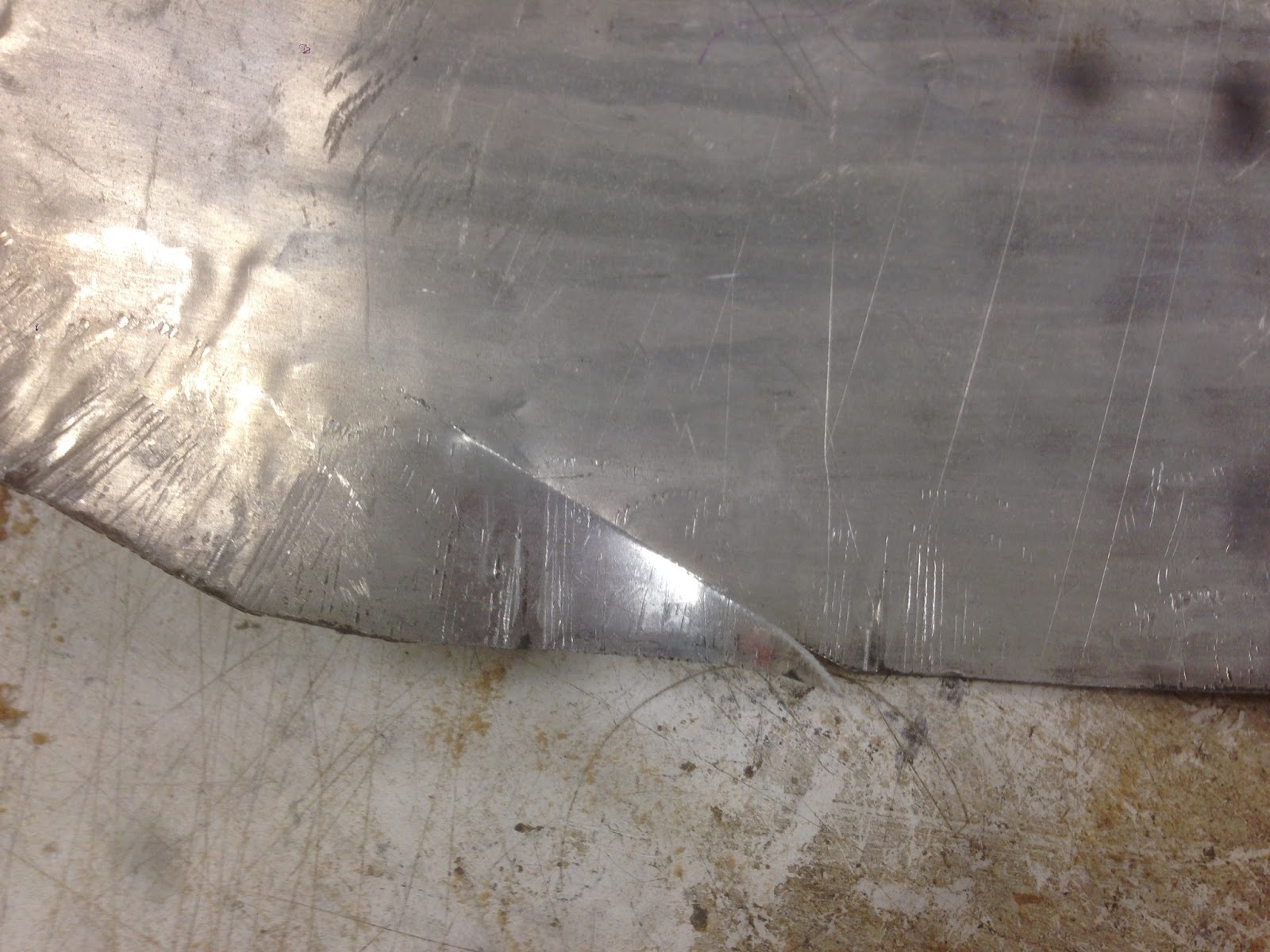
In order to fashion the ends of the sheet to meet with the edges of the laser cut template and ultimately reduce the remaining gaps, the flat faces adjacent to the curves were hit against a flat anvil to provide a stretch to the sheet of aluminium. This would allow for more metal to be 'played with', allowing for slightly more movement and to reduce the rigidity of the shape.


Flat face hit against flat anvil to 'stretch' the surface of metal sheet


The process of metal shaping for this interdisciplinary object was relatively easier to fabricate due to its simple shape with not too many 'movements' in profile. The difficulty of this object rose from the central curve of the shovel shape, which was quite small and therefore has a higher degree of curvature with the space that is available. This skin was relatively close to that of the template, with the curves matching quite well. The difficulty to replicate this shape does not stem from the shovel's dimensions or overall profile, but due to the method in which shovels are manufactured. As shovel blades are heated, pressed in machinery and other equipment, it is quite difficult to replicate the shape of the shovel using metal shaping tools and processes which are mainly catered towards more curved and organic shapes.